
- A fixed edge. Membrane stresses go to another structure: a building, soil,…

Tuwaiq Palace, Riyadh, Saudi Arabia
- A hard edge. The membrane stresses are transferred to a component that can support them. The most common one is a beam of rigid bar: a tube, a beam of wood,…

Holiday Inn in Palm Springs, Calif.
- A flexible edge. The membrane stresses are supported by a flexible element: a border cable so that the cable can withstand these stresses with a curvature. The greater curvature on the cable, the less tension in it. And vice versa; cables with low curvature have great tensions.

Eagle Point Amphitheatre
- Ridges. Turning points of the membrane creates a dihedral with concave side down. Resistive component of the ridge can be a curved cable with upward concavity, a straight beam or an arc with the concave side down. In case of beam and arc, the component must withstand bending or compression (for example a tube).
- Valleys. Turning points of the membrane, creating a dihedral with upward concavity. In general the valleys tend to use a curved cable with the concave side down. But obviously it could also be a beam or an arc.

Denver International Airport
- Material.
Vertex plates are often made of steel. Stainless steel when the budget allows or galvanized steel (painted or not) when not

Stainless Steel
- Form.
The basic form of a plate vertex is circular sector. This circular sector is determined by the aperture angle and radius. From this basic form you can derive many variations, generally lightening the plate through holes strategically placed to not diminish the strength of it. In addition to the surface form, these plates have a thickness suitable to provide adequate resistance to the loads.

Full and recessed plate
- Actions and Reactions.
A number of corner components are connected tothe plate. Some are loads transferring from the membrane and the edges and others are transferred by the reactions. The most common way to connect is:
-
- Membrane.A cover plate(made of the same material as corner plate) presses on the membrane with screws and a small rope which prevents the membrane can slip between the cover plate and the corner plate. Another more complicated possibility is to physically separate the membrane from the plate and join them with small clamps, cables, belts, etc. The number of these connections depends on the angle of opening of the plate and the force transferred.

Camp de Mart Auditorium, Tarragona
-
- Border cables.The simplest form is cable with a loop terminal and connect it with a shackle to a hole on the corner plate. This detail is inelegant and takes up much space, so it tends to use a more sophisticated solution that is to terminate the cable with a threaded swaged terminal which is inserted into a tube welded laterally to the plate. This last solution allows you to tighten the cables.

Loop terminal and schackle
-
- Pocket belts. Often, there is a load carrying belt attached to the membrane covered by the pocket and connected to the corner plate to prevent the pockets containing the border cables from sliding along the cable. In that case the solution is not as complicated as in the previous case and is usually provided by a ring terminal to the belt and a shackle connection with the plate.

Reinforcement with pocket belt
-
- Reactions. The main plate supports the actions of the borders of the membrane and transfers them to support. This is usually done with a single element (but could be more). a) It can be through a turnbuckle that connects to the plate by using a pin in a previously prepared hole. b) You can also use a shackle through this hole to connect with other parts. c) We have a hose directed towards the support, enter the threaded terminal where a cable that goes to such support. In this case must take into account where to place the thread of the threaded terminal. You can have screw terminal of a cable that enters a tube directed towards supporting and goes to support. In that case you must to consider how to connect the threaded terminal. d) We can place a plate perpendicular to the plate (or two) to take a U piece in the other direction. The previous solutions are very common, but obviously we can invent many more.
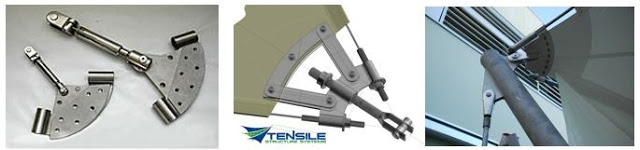
Different types of corner plates
-
- Continuous cable. When a corner plate gets two identical cables (or more if it is applied to the two external cables), we can use one continuous, uninterrupted cable rather than designing two terminals. It is a more economical solution but requires us to design a plate that matches the curvature of the cable. In that case, we can not tighten the two border cables independently.

Continuous cable

Too complicated detail
 WinTess, with its menu Other | Vertices plates, offers the possibility to get an idea of how they these plates will be, giving the main dimensions and generating a DXF file so that user can manipulate freely and create their own plates.

Menu: Other | Vertices plates
