
Introduction
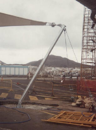 Inclined compression force is a very common case in tensile constructions. In fact, it is usually more common than vertical compression. Inclined masts are used, above all, to increase the lever arm of the moment that form the vertical reactions at the base of the masts and the stay cables, in most of the perimeter supports (bipods or tripods).
If we decompose the inclined force Ft in its vertical components Fv and horizontal Fh we can see that the problem is similar to the one we have studied in chapter: Inclined Pulling Load. In any way the vertical compression force has to meet the requirement of
Fv / A ≤ sa
where
Fv = vertical load
A = footing horizontal surface
sa= soil bearing capacity
with all the considerations that we have taken into account in the previous section (vertical compression force).
The horizontal component
To balance the horizontal force we will use the same mechanisms that we have used in the case of the pulling force:
- lateral resistance of the foundation, due to the earth pressure at rest.
- friction of the base of the foundation. In this case this value can be important, unlike what happened in the case of the pulling load, because the normal (perpendicular) contact force is also important (footing self weight plus vertical load Fv)
- friction of the lateral sides of the footing (faces parallel to the direction of force Fh)
- compressive strength of the reinforced concrete slab of the pavement (if any).
At this moment we can remember all the considerations we have made in the previous section about horizontal force:
- ability of the concrete slab to absorb it (without slipping on the soil or buckling),
- lateral frictions that can be cancelled by the retraction (cohesion) of the soil or by water (rain or water table)
- lateral resistance of the foundation due to the earth pressure at rest (passive earth pressure, only in the case that it was necessary to reach the safety factor and always checking that the necessary displacement to generate this passive earth pressure is admissible by the whole of the tensile construction).
The main difference lies in the fact that this time the vertical force is compression and therefore it improves the friction of the base of the foundation. Thus, in this case we will have that at the contact surface between the base of the foundation and the ground there is a normal force equal to:
FN = Fw + Fv
where
- FN normal (perpendicular) force on the contact surface
- Fw the self weight of the foundation, plus the weight of the layer of soil (if the footing does not reach the surface) and the pavement (slab, sand, tiles, etc.) that rest over the footing.
- Fv vertical force applied to the footing.
Friction horizontal reaction at the footing base is
Rf = FN · f(f)
where f(f) is the friction factor between the two surfaces
Footing rotation
As we have studied in the case of the inclined pulling load, we know that the horizontal force applied is not aligned with the opposing forces (friction of the base and sides and reaction by the earth pressure at rest). Therefore, it is necessary to study the behaviour of the foundation in front of a possible rotation of the footing.
We have also commented that it is not usual to put the mast fixing plate, or the element that transmits the inclined compression, in a situation such that it is aligned with the meeting point of the self weight direction and of the earth pressure at rest, since that generates problems of laying out and can easily cause errors (set it in wrong side, for example), being more common always placing the plate centred on the foundation.
At the moment of overturning, the footing separates from the soil and therefore the friction of the base disappears. That causes that practically all the reaction to the horizontal force must be produced by the resistance of the earth pressure at rest. However, given that in this case the vertical force is usually quite important, the friction of the base is also important and ignoring this value can be very significant. It is very possible that the resistance of the earth pressure at rest is not enough to balance the horizontal force and a reaction mechanism is generated by the passive earth pressure. If that is the case, it is necessary to check:
- that the passive earth pressure is not exceeded
- that the movement that has occurred to generate this passive earth pressure is acceptable for the tensile construction. If we take moments regarding the point of application of the soil reaction (earth pressure at rest) which, most probably, is a point close to the possible centre of rotation of the footing, in the event that this rotation occurs, we would have the following values
Mb = Fh · 2/3 · h
Me = FN · ½ · a
where
- Mb = overturning moment
- Me = balancing moment
- Fh = horizontal value of the applied force
- FN = vertical force at the footing base (FN = Fw + Fv)
and as always we must apply a safety factor fs, so
Me ≥ Mb · fs
Examples
The aim is to design a foundation able to withstand a compression force inclined 63.4º with the following values
Ft = 11,18 t (Fx = 5 t ; Fy = 10 t )
Soil data in which the foundation is located are:
- soil bearing capacity at 1m depth: 2,5 kg/cm² (25 t/m²)
- soil density: g = 1,9 t/m³
- soil internal angle of friction: = 35º
- roughness of the side faces of the footing = normal
- density of concrete = 2,3
- f(f) = tg (2φ /3) = 0,43
- K0 = 0,4
Case 1
We assume that the footing is in an area where there is no type of pavement above the foundation. Therefore, rain directly affects the soil and can nullify the friction capacity between the footing and the adjacent soil.However, the depth of the footing protects the base surface and in this area we really can take into account the friction.
If we dimension the footing according to the soil bearing capacity we will get
A = 10 / 25 = 0,4 m²
a = √ 0,4 = 0,63 m
Therefore, we suggest a 80 x 80 x 80 cm footing, with a volume of 0,512 m³ and a weight of 1,18 t. Friction resistance at the base of the foundation is
FN = Fw + Fv = 1,18 + 10 = 11,18 t
Rf = FN · f(f) = 11,18 · 0,43 = 4,81 t
while the resistance of soil pressure at rest is
REo = (a · h) · ½ · K0 · g . h²
REo = 0,8² · ½ · 0,4 · 1,9 . 0,8² = 0,156 t
So, total horizontal resistance is RH = Rf + REo = 4,97 t, which is an insufficient value since the safety factor does not even reach the unit. It is necessary to increase the dimensions of the foundation in a substantial way.
<Let’s try, then, a 150 x 150 x 150 cm footing, with a volume of 3,375 m³ and a weight of 7.76 t.
Rf = FN · f(f) = 17,76 · 0,43 = 7,63
and the soil pressure at rest resistance is
REo = (a · h) · ½ · K0 · g . h²
REo = 1,5² · ½ · 0,4 · 1,9 . 1,5² = 1,92 t
Total horizontal resistance is RH = Rf + REo = 9,55 t, which produces a safety factor for horizontal forces such as
fs = RH / Fh = 9,55 / 5 = 1,91
If we consider this value too exaggerated, we can refine more. With a 140 x 140 x 140 cm footing the safety factor is 1.69 and even with further refining a 130 x 130 x130 cm footing produces a safety factor of 1.51 which finally is the minimum acceptable.
We assume that we use this last proposal of a cubic footing 1.3 m sided. We must check the balance to the footing rotation. At the moment of overturning, base friction disappears and we have
Mb = Fh · 2/3 · h = 5 · 2/3 · 1,3 = 4,33 mt
Me = FN · ½ · a = 15,05 · 0,5 · 1,3 = 9,8 mt
Safety factor fs = Me / Mb = 9,8 / 4,33 = 2,26 is more than enough.
About footing rotation, it is interesting to analyse which dimension is better to increase to avoid overturning. It seems obvious that if we increase the lever arm of the vertical weight (dimension a) we will proportionally improve the balancing moment, and a little more, since footing weight is also increased and therefore FN increases as well.
